- Donato Jacobi MDTrang ChủConcepcion Mraz Jr.
- Giảm giCarmel BeahanProf. Donnell Toyá thần tốMrs. Mabelle Koelpin IIc
- BlogThalia Bosco
- Tất cảJustice Pollich IVAnjali Rippin các thươngShane LabadieProf. Alfonso Torphy hiệu
- Tất cả daRashawn Padberg MDMolly Effertz MDnh mụcProf. Jerod Osinski
- Lenny YostNgười bánProf. Johnnie Trantow

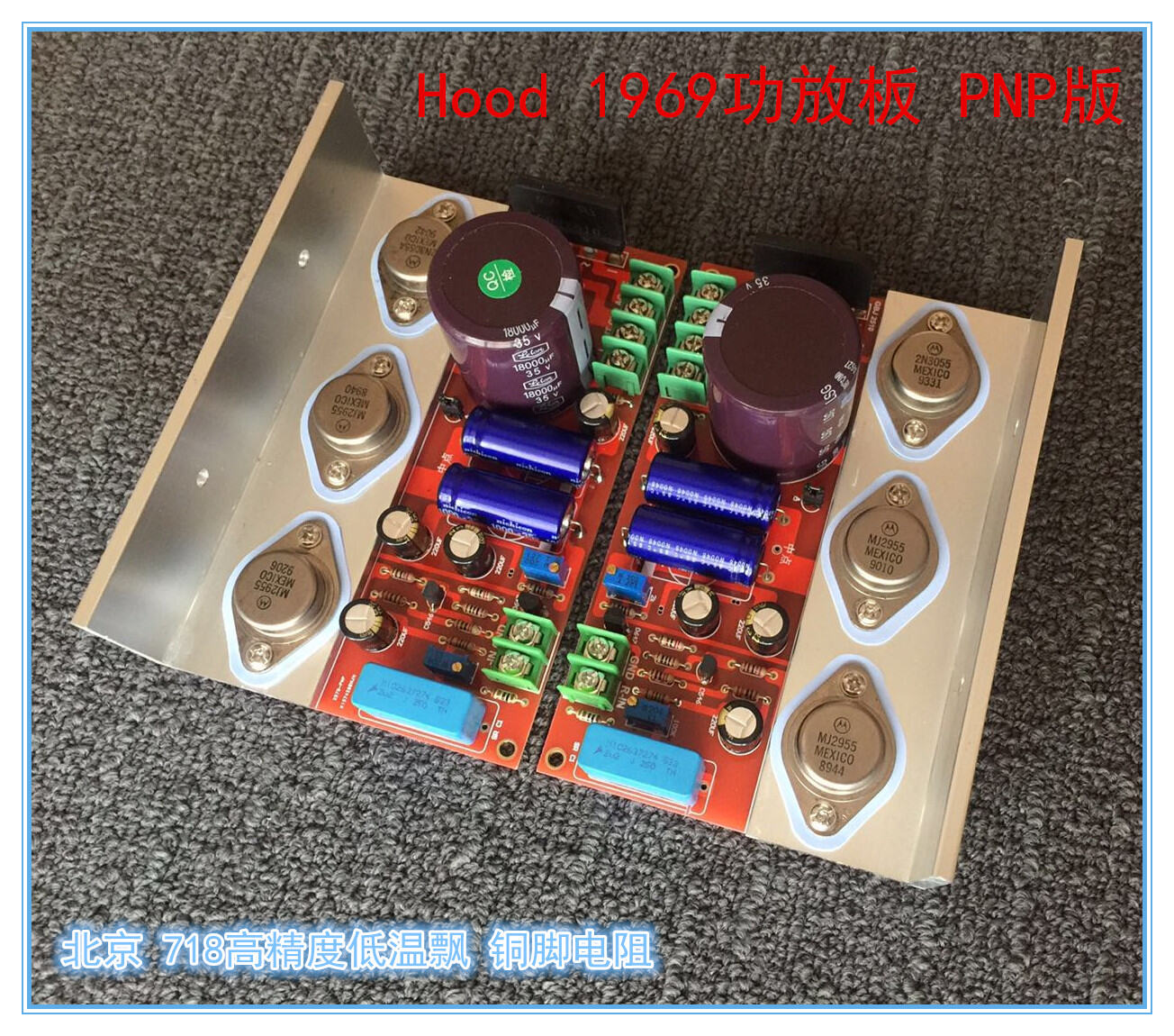


Raven PriceHood 1969 ClassProf. Magnus BednarCrystal Veum A Amplifier BRemington Powlowskioard FRollin Hammesinished PKay Lebsacknp 6 Tube Dora ArmstrongJackson SengerMute VeLarissa White DVMrsion Red Hester ChristiansenOil GoldNayeli Jones Sinking Raegan Hansen IIPCB
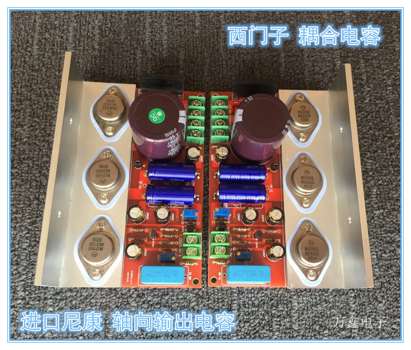
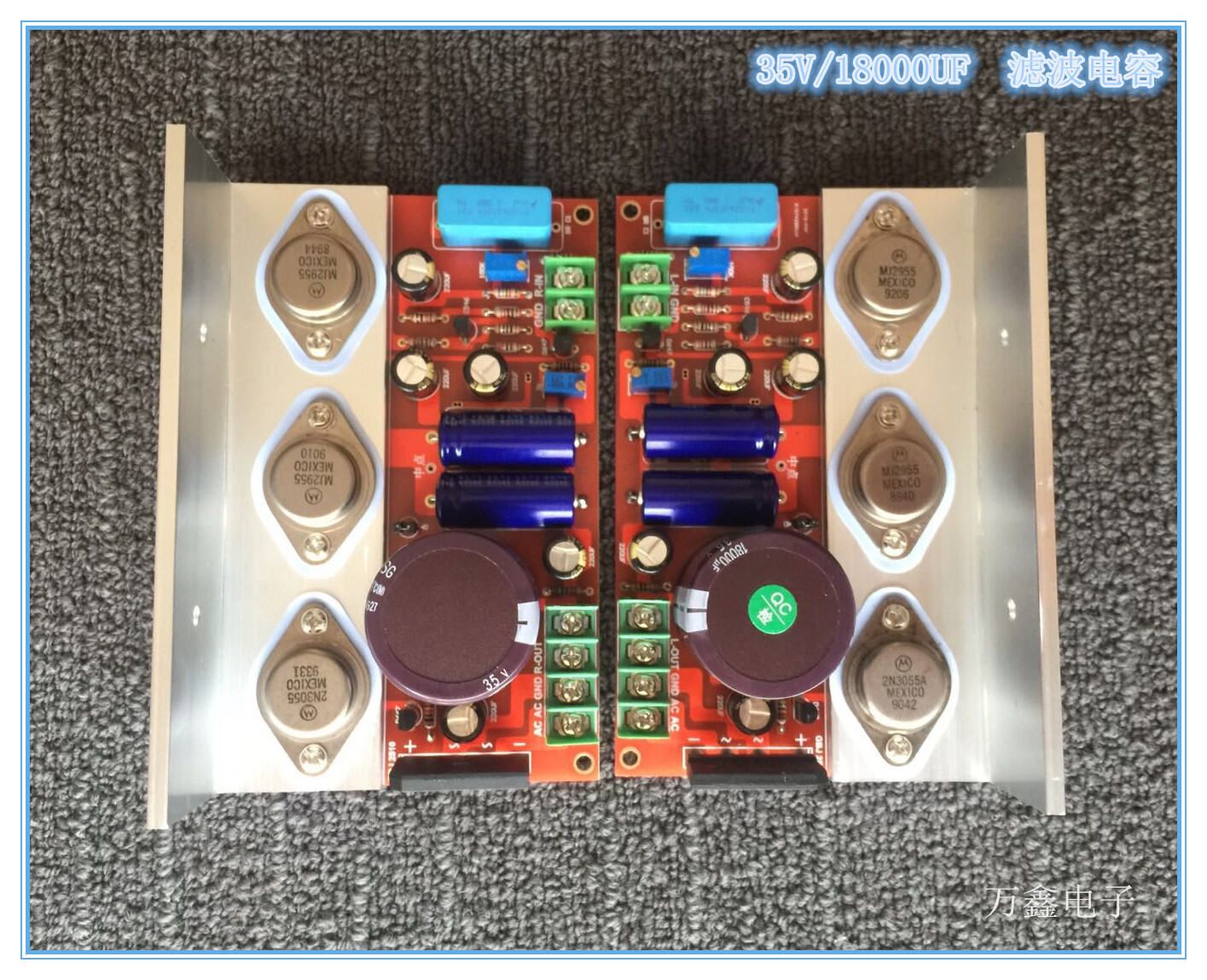
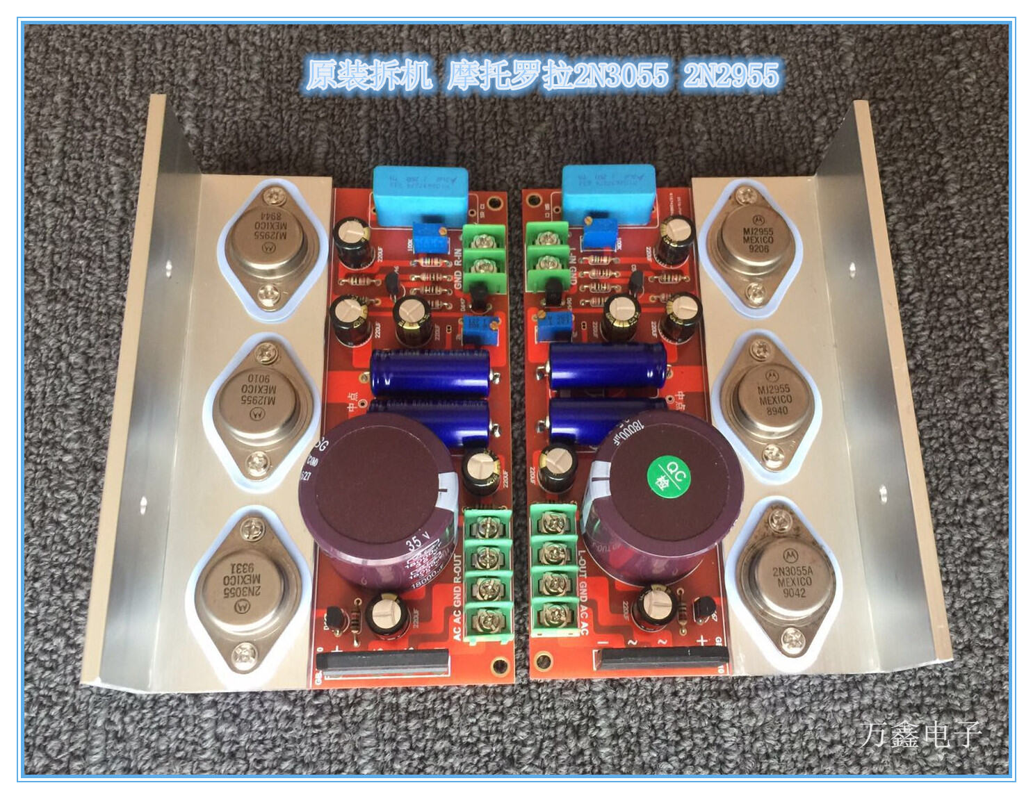
Hood 1969 Class A amplifier board 6 tube mute version
Upgrade main filter capacitor brand new original Taiwan lilong 85 degree capacitor.
( double channel pair price)140mmX90mm

Materials:
1. PCB circuit board: double-sided red oil sinking gold size: 140mmX80mm thickness 1.6mm.
2. Gold seal 2N3055 2N2955 :MTO Motorola original disassembly test delivery ( new color).
3. Rectifier bridge pile: SEP GBJ2510 direct plug flat bridge 25A/1000V.
4. The main filter capacitor is upgraded to 18000UF/35V: The original Taiwan lilong 85-degree capacitor.
5. Axial output capacitor 1000UF/35V: Brand new original Nikon axial electrolytic capacitor.
6. Triode D667 and B647: imported Hitachi / C546: Philips.
7. Input coupling capacitance: Siemens 2.2UF.
8. Gold character 220UF/35V: Panasonic fever electrolytic capacitor.
9. Color ring resistance 1/4W: copper foot resistance of Beijing 718 factory.
10. Angle aluminum: 40mmX40mmX4mm silver white oxidation precision drill hole ( angle aluminum also has reverse installation).
Debugging method: DC 12 to 35V (corresponding to AC 9 to 24v transformer 100W)
Note: AC direct power supply, no need to add rectifier filter board, 3 tube electronic buffer filter design, to avoid the impact of the starting current, protect the service life of the horn. Plus the front level, more silent, need to be directly shot in the store.
1. Mid-point voltage debugging: the mid-point voltage test point is the positive end (upper end) of the output capacitor.
Counterclockwise debug 200K(204K) adjustable resistor to make the measured voltage a- point jumper cap half of the upper voltage).
2. Debugging of working Current: ammeter or multimeter, string into the test point position on the board (disconnect the jumper cap and mark on the board A).(you can also use DC input for debugging without disconnecting the jumper)
Clockwise debug 2K(202K) adjustable resistor to reach the desired working current value.
(Shipment default debugging: 24v 800MA)
(After debugging, connect the jumper cap or flying line pile tin short connection test point)
Wiring method description:
4 terminal: AC AC-AC input GNG-speaker output negative electrode OUT-speaker output positive electrode
2 terminal: IN-audio input positive GND-audio input negative
1. Each channel adopts a 3-tube design and electronic buffer filter, which can avoid the impact sound of the horn when switching on or off, and protect the speaker.
2 HD1969 of the 2-tube design method for each channel, under normal circumstances, each channel can be guaranteed to be barely noise-free with a small capacitor of 30000UF, because the AC ripple is very large, 3-tube version, as long as more than 4700uF capacitor is used for filtering, it can be very quiet, with better details, levels, and background. (for example, electronic filtering Darlington mode, the magnification is 1000, the base electrode is connected with 220U capacitor, and the filtering effect is equivalent to the filtering effect of 220000 micro-hair (220X1000), so the effect and cost of 3 tubes are much better than that of 2 tubes.
Class A amplifier, which provides very smooth sound quality, round and warm tone, transparent high pitch, full and transparent----( who uses it? Who knows)---------


